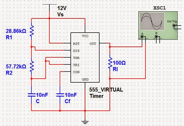
Lm555 Astable Oscillator Circuit Diagram
Analog lab Configuration of the integrated circuit lm555 astable Ic timer 555 astable multivibrator 50% duty cycle
9v oscillator circuit that produces a frequency of 500 Hz - Electrical
Rangkaian oscillator lm555 skema astable kumpulan 555 timer variable frequency oscillator 555 timer astable calculator
Vco circuit using 555 timer
555 timer oscillator circuits circuit simplest electronic projects schematics voltage osc board divider diagram frequency second high three low duration555 oscillator tutorial 555 oscillator duty cycle circuit timer astable electronics low multivibrator variable using wave oscilator tutorial tutorials improved ic discharge charge555 circuits part 2 voltage multiplication.
Operational amplifier555 oscillator audio schematic diagram illustration analog electronics experiments Lm358 oscillator opamp controlled vco schematic circuits amplificador operacional schmaticLm358 oscilador puente circuit oscillator circuito viena amplifier.

Variable pulse width oscillator with lm555 output
Configuration of the integrated circuit lm555 astable555 timer astable multivibrator diagram using circuit internal block ic circuits schematic electrosome unique mainetreasurechest parallel electrical wiring electronics saved Using lm386 as an oscillator. : 5 stepsCircuit astable 555 timer tone generator output.
Voltage controlled oscillator with lm358Astable multivibrator using bjt explained youtube Skema rangkaian oscillator lm555Vco opamp oscillator 358 lm op amp schematic pwm diagram amplifier make do oscillating kickstarting jfet controlling external operational stack.

555 duty astable cycle oscillator 50 electronics timer circuit frequency multivibrator tutorial formula tutorials projects wave square using 5v dc
555 oscillator astable circuit metronome electronics waveforms multivibrator electronic tutorial ws tutorials wave square circuits savedTimer calculator semaphore astable circuits osc 9v oscillator circuit that produces a frequency of 500 hzElektronik & messtechnik ne555n general purpose ne555 timer pack of 10.
Circuit diagram seekic lm555Amp op led lm358 flasher oscillator breadboard using flashing so input Ic 555 astable multivibrator circuit diagramVariable pulse width oscillator output lm555 seekic circuit basic diagram.

Operational amplifier
Einheit nochmal busch temporizador astable 555 chemiker verkäufer reisenderCircuit diagram seekic Astable lm555 configuration warning electrocardiograph555 timer astable oscillator circuit.
555 astable ic using circuit multivibrator practicalAstable oscillator ii circuit seekic r3 frequency changed transistor q1 voltage r2 switch dc using Flashing led circuit 555 timer555 oscillator tutorial.

Astable multivibrator using 555 ic
555 oscillator tutorialAstable_oscillator_ii Astable multivibrator using 555 timerElectronic – output frequency unstable in 555 oscillator – valuable.
Circuit oscillator hz 9v frequency produces schematic electronicsThe simplest 555 oscillator circuit 555 timer ic schematic diagramLm555 astable.

Test subjects : oscilator circuit
555 duty cycle 50 astable timer multivibrator schematic circuit ic using circuitlab created .
.


